The Role of the Compressor

The Role of the Compressor

Think back to the hot heat exchanger and the black grille behind the refrigerator. The fact that this heat exchanger is warm means that the fluid passing through is also warm. The function of this heat exchanger is to cool the gaseous R22 so that it condenses.

As a reminder, the evaporator is the cold heat exchanger in which the refrigerant evaporates. By the same analogy, the hot heat exchanger in which the gas condenses is called the condenser.

In our incomplete refrigerator, at the evaporator outlet, the gaseous R22 find itself in the open air at atmospheric pressure at a temperature of -42°C.

If we had passed this vapour at -42°C directly into the condenser, do you think cooling of the vapour would occur?

fridge evaporator coil heat transfers

Remember that heat passes from hotter bodies to colder bodies.

The temperature is well above the refrigerant in the kitchen, where the fridge is at about 20°C. Under these conditions, how can it cool vapour at -42°C with air at 20°C?

As we know, to condense the vapour, We must cool it. Therefore, to condense gaseous R22 at -42°C, it is essential to cool it to a temperature less than -42°C!

Since the kitchen is about 20°C, condensation is impossible. What, then, can we do? We must either cool the kitchen to below -42°C (which would appear impossible to do cost-effectively) or heat the R22 vapour to a temperature above 20°C.

We now have a new problem. We must heat the R22 vapour from the evaporator at -42°C before passing it into the condenser.

What can we do to heat the vapour? Do you have any ideas?

Before answering the questions, let’s perform a new experiment to get us on the right path.

Take an ordinary bicycle pump. In the first instance, operate the pump without blocking the outlet. Then pump it whilst covering the outlet with your thumb: what do you notice?

bicycle hand pump

Be careful. I almost burnt myself performing this experiment!
Although your thumb is blocking the outlet, the air still manages to escape.

What happens as soon as the pressure of the air becomes greater than that exerted by your thumb? The air can escape!

But there’s another critical observation that we should make: the temperature of the trapped air increases noticeably.

bicycle hand pump experiment

To obtain a better understanding of what’s happening, let’s discuss the inside of this bicycle pump.

Inside the pump is a piston that slides into the cylinder or barrel of the pump.

When we partially obstruct the pump’s nozzle, the pressure in the cylinder rises, as does the pump’s temperature.

The air can escape when the pressure builds up inside the cylinder and becomes significant enough.

This simple experiment demonstrates that it heats up when we compress a gas.

Now, our problem is how to heat the R22 vapour at -42°C to higher than the ambient temperature in the kitchen.

If we heat the refrigerant vapour this way, it will become hot enough to allow the air in the kitchen to cool the vapour. It would then enable the vapour to condense.

Here’s a Solution to our problem: we need to heat the refrigerant between the outlet of the evaporator and the entry of the condenser, so all we need to do is compress the vapour!

The compression of gas causes an increase in its pressure and also an increase in its temperature.

Naturally, we won’t be using a bicycle pump in our fridge! But whilst we’re on the subject, do you know where the pump we use in a refrigeration system is and what is its correct name?

The refrigeration “pump” is at the back of the fridge, just below the condenser. It’s e sort of black pot, Which is completely airtight with some tubes and electrical wires attached.

This “pump”, which allows us to compress the refrigerant in the system, is known as the compressor.

fridge compressor

Just as we observed when we examined the interior of the bicycle pump, a standard reciprocating compressor has pistons and cylinders. But, of course, the compressor isn’t driven by hand but uses an electric motor.

Apart from this feature, the principles of operation for such compressors are practically identical to those of a bicycle pump: The piston compressor bears a close resemblance to a motorised bicycle pump!

Just as with a bicycle pump, the function of every compressor is to take in vapour, compress it and then pump it out again at a higher temperature and pressure. Now let’s examine the diagram showing us the principles of a piston compressor.

There are two connections to the refrigeration system. First, at (1), we find the intake to the compressor through which it draws in vapour to compress.

After compression, the vapour will be at a higher pressure through the pipework connected to (2).

As the pressure must always be higher on side (2) than side (1), we talk of the Low Pressure (LP) intake or suction side and the High Pressure (HP) outlet or discharge side.

At (3), we find the inlet valve (which is also called the LP valve) and at (4), the outlet or exhaust valve (HP valve). These valves are small flexible strips or reeds of thin steel.

compressor components

At (5), you will recognise the piston, which slides up and down in the cylinder (6). The piston connects through a connecting rod (7) to an eccentric crank (8). The function of this assembly is to convert the crank’s rotary movement into a linear piston motion. As the electric motor turns the crank, the piston should continually rise and fall in the cylinder.

Now we’ll examine what occurs in a compressor during one piston stroke. After that, we’ll look at each stage separately to fully understand what’s happening.

Figure A. The compressor has stopped, and the piston is right at the bottom of the cylinder (this particular point, below which the piston cannot move, is called the bottom dead centre). Cylinder (6) is now full of R22 vapour at low pressure (LP).

compressor components working

Figure B. The compressor starts. The crank then starts to rotate and, in turn, begins to operate the connecting rod. It causes the piston to rise progressively, and as the piston rises, the pressure in the cylinder (6) starts to increase.

The valves (or reeds) are made up of thin strips of flexible steel, and are attached by one end to either side of a plate (9) located at the top of the cylinder (this plate is called the valve plate). Note that the LP and HP permanently exert pressure on the top of their respective valve reeds. We will see that these pressures are relatively stable.
compressor valves
In contrast to this, the pressure that exists inside the cylinder (6) is exerted against the underside of each valve reed. Unlike the LP and HP, the pressure inside (6) is constantly changing, according to the position of the piston. For example, the higher the piston rises, then the more the pressure in the cylinder rises. Let’s look at how the pressure that exists in the cylinder affects the position of the valve reeds.

If the pressure inside the cylinder becomes greater than the HP, the HP valve opens (in actual fact, the reed bends upwards, allowing the R22 to escape from the cylinder and leave via the HP pipework). Note that the pressure in (6) is greater than the LP, so the inlet valve remains closed and effectively gas-tight.

In contrast, if the pressure in cylinder (6) becomes less than the LP, the LP valve reed opens (in effect, it bends downwards and allows R22 from the LP pipework to enter the cylinder). Since the pressure in (6) is much lower than the HP, the outlet valve stays closed and gas-tight.

compressor valves low pressure opens

In this manner, the valve reeds can open and close in a way that is solely dependent on the pressure that exists in the cylinder: the refrigerant pressures control the valves.

Try to understand the diagram below, which shows the piston in different positions during its movement in the cylinder.

compressor reciprocating

From (B) to (C), the crank turns, and the piston rises further and further in the cylinder whilst compressing the R22 vapour. The pressure and temperature of the gas in the cylinder increase gradually as the piston rises in the cylinder.

At (C), when the pressure in the cylinder becomes just greater than the HP, the outlet valve reed opens, and the compressed gas discharges into the HP pipework. Note that the LP valve is in the close position and gas-tight whilst all this is happening.

compressor reciprocating b to c

From (C) to (D), The piston continues to discharge the HP vapour, but when we get to (D), the piston is right at the top of the cylinder. The top dead centre is the point above which the piston can not move anymore.

As the piston cannot rise any further, the pressure in the cylinder equilibrates with the HP, and the outlet valve closes.

Note that a top dead centre still has a space between the piston and the valve plate. This gap, called the “dead space”, the “clearance space”, or “clearance volume”, is essential to prevent the piston from “knocking” into the valve plate. You should also note that this clearance volume is still full of gas at high pressure (HP) at the top dead centre.

compressor reciprocating c to d

At D (top dead centre), the crank continues to rotate, and the piston starts its descent.

compressor reciprocating d to b

At D (top dead centre), the crank continues to rotate, and the piston starts its descent.

At D, the piston is at the top dead centre. That is, it cannot move any higher in the cylinder. It is because both valves close, and some HP vapour traps are in the clearance space. As the crank continues to tum, the piston starts to fall again in the cylinder.

At this point, what happens to the pressure in the cylinder?

Look at the diagram opposite: in (1), some gas is enclosed. When we move the piston up to position (2), the pressure in the enclosed space increases. If we bring the piston back to (1), the pressure in the closed volume returns to its initial value.

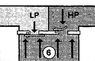
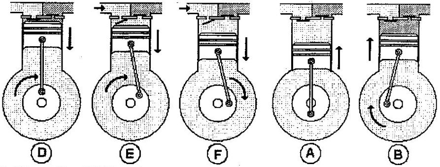
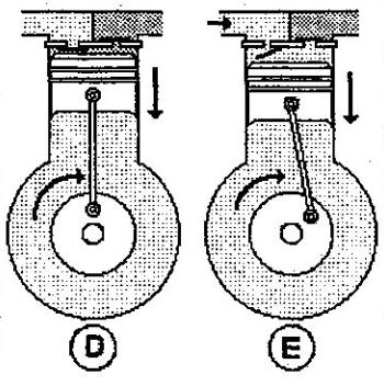
As soon as the piston moves downwards, the pressure of the trapped gas in the cylinder starts to fall. But, of course, as soon as the pressure in the cylinder is just below LP, the intake valve opens, and the compressor draws refrigerant into the cylinder shown in (E).

The LP valve remains open like this throughout the descent of the piston (F).

At point (A) (bottom dead centre), since the piston can descend no further, the pressure in the cylinder equilibrates with the LP, and the inlet valve closes.

At this point, the cylinder is completely full of LP vapour, and we have returned to our original starting point: the crank continues to rotate, and the piston rises and compresses the LP vapour. Then, it discharges again on the HP side.

In summary, for each turn of the crank, the piston moves backwards and forwards once, drawing in LP vapour and discharging it on the HP side.

compressor reciprocating f to a

For your information, many compressors have a rotation speed of 2800 rpm. It means that the piston rises and then descends 2800 times per minute, close to 47 times per second. It also means that each HP and LP valve reed opens and closes nearly 47 times per second!

Back to Basic!

Related

Scroll to Top